YKUSH3 I2C
YKUSH3 I2C Tutorial
What we will be using in this tutorial
- Two YKUSH3 boards
- A computer (PC) with ykushcmd installed
- Two USB cables for connecting each YKUSH3 to the upstream USB host (PC)
- 2.54mm pin headers to solder into the YKUSH3 I2C breakout pins
- Connection wires to interconnect the boards I2C pins
Why do we use two YKUSH3? For convenience, we will be using one configured as a I2C master and the other as slave.
A brief overview of I2C
I2C it’s a two wire master-slave communication protocol, where one wire is the serial clock (SCL) and the other is the serial data (SDA).
Masters generate the clock and address the slaves. Slaves receive the address and clock. Both master and slave can transmit and receive.
Each slave has a unique address. Multiple slave devices can be linked together and addressed by the same master. For the purposes of this tutorial we will call these connections the I2C Bus.
Addresses can be 7-bit or 10-bit in length. YKUSH3 use 7-bit addresses so we will not cover 10-bit addresses in this tutorial.
Bellow an illustration of a I2C frame as a timing diagram.

I2C in the YKUSH3
YKUSH3 I2C is user configurable as master or slave. The configuration is done using ykushcmd control application.
YKUSH3 with I2C in master mode
When I2C master mode is enabled YKUSH3 serves as a gateway between the USB host and the I2C bus. This allows you to communicate with a I2C slave device from a PC using a YKUSH3 board.
YKUSH3 with I2C in slave mode
When I2C slave mode is enabled the YKUSH3 can be controlled from the I2C interface. This is useful if you want to control a YKUSH3 from a microcontroller device, or any device with a I2C master interface.
YKUSH3 use 7-bit I2C slave addresses. The boards are factory programmed with slave address 0x53, in hexadecimal representation (0b1010011 in binary representation). The address are user configurable using the ykushcmd.
Our setup
To illustrate the use of YKUSH3 both in I2C master and slave mode we set up the following system.
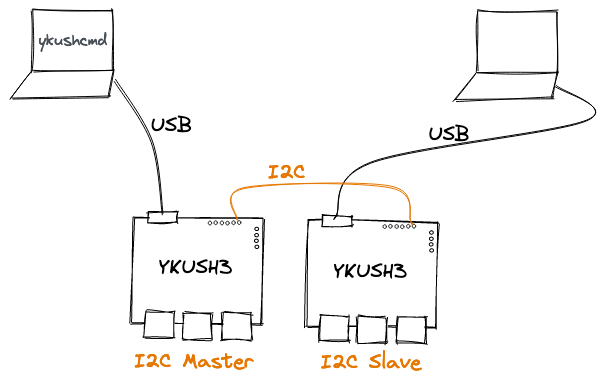
We have two YKUSH3 boards, one configured as I2C master and the other as I2C slave. Each is connected to a PC.
To control the board configured as slave an I2C master device is needed. For that we use the other YKUSH3 board with I2C master mode enabled.
With this setup we can control the downstream ports of the YKUSH3 connected to the second PC by issuing ykushcmd commands in the first PC.
Start by configuring one board as I2C master and the other as slave. Connect one board to a PC and run the following command to configure it as I2C master.
ykushcmd ykush3 --i2c-master enable
Connect the other board to a PC and run the following command to configure it as I2C slave.
ykusckmd ykush3 --i2c-slave enable
Now that they are properly configured wire them in the I2C interface. Start by connecting both boards to the same electrical ground level by wiring a GND pin of one board to a GND pin of the other. Then connect the SCL pin of one board to the SCL pin of the other board. Do the same to the SDA pins. Finally attach one board to a PC and the other board to another PC.
In the PC to which the board configured as master is connected to, issue the following command to switch off the downstream 1 of the board configured as I2C slave.
ykushcmd ykush3 --i2c-write 0x53 0x07
In the examples above the factory programmed address 0x53 was used. This works fine in our setup because only one YKUSH3 I2C slave is connected to the I2C bus. But if you wanted to have more than one YKUSH3 slave one of the boards must be configured with a different address. Let’s change the address of the slave board from 0x53 to 0x54.
Do the following in the PC to which the slave board is connected to.
ykushcmd ykush3 --i2c-set-address 0x54
Now to switch off the port 2 of the slave board run the following command in the PC to wich the master board is connected to.
ykushcmd ykush3 --i2c-write 0x54 0x08